Product Description
|
Material |
1) Aluminum: AL 6061-T6, 6063, 7075-T etc. |
|
2) Stainless steel: 303,304,316L, 17-4(SUS630) etc. |
|
|
3) Steel: 4140, Q235, Q345B,20#,45# etc. |
|
|
4) Titanium: TA1,TA2/GR2, TA4/GR5, TC4, TC18 etc. |
|
|
5) Brass: C36000 (HPb62), C37700 (HPb59), C26800 (H68), C22000(H90) etc. |
|
|
6) Copper, bronze, Magnesium alloy, Delrin, POM,Acrylic, PC, etc. |
|
|
Finish |
Sandblasting, Anodize color, Blackenning, Zinc/Nickl Plating, Polish. |
|
Power coating, Passivation PVD, Titanium Plating, Electrogalvanizing. |
|
|
Electroplating chromium, electrophoresis, QPQ(Quench-Polish-Quench). |
|
|
Electro Polishing,Chrome Plating, Knurl, Laser etch Logo, etc. |
|
|
Main Equipment |
CNC Machining center(Milling), CNC Lathe, Grinding machine. |
|
Cylindrical grinder machine, Drilling machine, Laser Cutting Machine,etc. |
|
|
Drawing format |
STEP,STP,GIS,CAD,PDF,DWG,DXF etc or samples. |
|
Tolerance |
+/-0.01mm ~ +/-0.05mm |
|
Surface roughness |
Ra 0.1~3.2 |
|
Inspection |
Complete inspection lab with Micrometer, Optical Comparator, Caliper Vernier,CMM. |
|
Depth Caliper Vernier, Universal Protractor, Clock Gauge, Internal Centigrade Gauge. |
|
|
Capacity |
CNC turning work range: φ0.5mm-φ150mm*300mm. |
|
CNC milling work range: 510mm*1571mm*500mm. |
/* January 22, 2571 19:08:37 */!function(){function s(e,r){var a,o={};try{e&&e.split(“,”).forEach(function(e,t){e&&(a=e.match(/(.*?):(.*)$/))&&1
| Application: | Fastener, Auto and Motorcycle Accessory, Hardware Tool, Machinery Accessory |
|---|---|
| Standard: | GB, EN, API650, China GB Code, JIS Code, TEMA, ASME |
| Surface Treatment: | Anodizing |
| Production Type: | Mass Production |
| Machining Method: | CNC Machining |
| Material: | Nylon, Steel, Plastic, Brass, Alloy, Copper, Aluminum, Iron |
| Samples: |
US$ 20/Piece
1 Piece(Min.Order) | |
|---|
| Customization: |
Available
| Customized Request |
|---|

What maintenance practices are essential for prolonging the lifespan of PTO shafts?
Maintaining proper care and performing regular maintenance on Power Take-Off (PTO) shafts is crucial for prolonging their lifespan and ensuring optimal performance. By following essential maintenance practices, you can prevent premature wear, identify potential issues early on, and maximize the longevity of your PTO shafts. Here are some key maintenance practices to consider:
1. Regular Inspection: Perform routine visual inspections of the PTO shaft to check for any signs of damage, wear, or misalignment. Look for cracks, dents, bent sections, or loose components. Inspect the universal joints, coupling mechanisms, protective guards, and other associated parts. Pay attention to any unusual noises, vibrations, or changes in performance, as these can indicate underlying issues that require attention.
2. Lubrication: Proper lubrication is essential for the smooth operation and longevity of PTO shafts. Follow the manufacturer’s recommendations regarding lubrication intervals and use the recommended lubricant type. Apply lubrication to the universal joints, CV joints (if applicable), and other moving parts as specified. Regularly check for adequate lubricant levels and replenish if necessary. Ensure that the lubricant used is compatible with the shaft material and does not attract dirt or debris that could cause abrasion or damage.
3. Cleaning: Keep the PTO shaft clean and free from dirt, debris, and other contaminants. Regularly remove any accumulated dirt, grease, or residue using a brush or compressed air. Be particularly diligent in cleaning the universal joints and areas where the shaft connects to other components. Cleaning prevents the buildup of abrasive particles that can accelerate wear and compromise the shaft’s performance.
4. Guard Inspection and Maintenance: Check the protective guards and shields regularly to ensure they are securely in place and free from damage. Guards play a critical role in preventing accidental contact with the rotating shaft and minimizing the risk of injury. Repair or replace any damaged or missing guards promptly. Ensure that the guards are correctly aligned and provide sufficient coverage for all moving parts of the PTO shaft.
5. Torque and Fastener Checks: Periodically inspect and check the torque of fasteners, such as bolts and nuts, that secure the PTO shaft and associated components. Over time, vibration and normal operation can loosen these fasteners, compromising the integrity of the shaft. Use the appropriate torque specifications provided by the manufacturer to ensure proper tightening. Regularly verify the tightness of fasteners and retighten as necessary.
6. Shear Bolt or Slip Clutch Maintenance: If your PTO shaft incorporates shear bolt or slip clutch mechanisms, ensure they are functioning correctly. Inspect the shear bolts for signs of wear or damage, and replace them when necessary. Check the slip clutch for proper adjustment and smooth operation. Follow the manufacturer’s recommendations regarding maintenance and adjustment of these safety mechanisms to ensure their effectiveness in protecting the driveline components.
7. Proper Storage: When the PTO shaft is not in use, store it in a clean and dry environment. Protect the shaft from exposure to moisture, extreme temperatures, and corrosive substances. If possible, store the shaft in a vertical position to prevent bending or distortion. Consider using protective covers or cases to shield the shaft from dust, dirt, and other potential sources of damage.
8. Operator Training: Provide proper training to operators on the correct operation, maintenance, and safety procedures related to the PTO shafts. Educate them about the importance of regular inspections, lubrication, and adherence to recommended maintenance practices. Encourage operators to report any abnormalities or concerns promptly to prevent further damage and ensure timely repairs or adjustments.
9. Manufacturer and Expert Guidance: Consult the manufacturer’s guidelines and recommendations regarding maintenance practices specific to your PTO shaft model. Additionally, seek advice from experts or authorized service technicians who are knowledgeable about PTO shaft maintenance. They can provide valuable insights and assistance in implementing the best maintenance practices for your specific PTO shafts.
By following these maintenance practices, you can extend the lifespan of your PTO shafts, optimize their performance, and reduce the likelihood of unexpected failures or costly repairs. Regular inspections, lubrication, cleaning, guard maintenance, torque checks, and proper storage are all essential in ensuring the longevity and reliability of your PTO shafts.

How do PTO shafts handle variations in load and torque during operation?
PTO (Power Take-Off) shafts are designed to handle variations in load and torque during operation by employing specific mechanisms and features that ensure efficient power transfer and protection against overload conditions. Here’s a detailed explanation of how PTO shafts handle variations in load and torque:
1. Mechanical Design: PTO shafts are engineered with robust mechanical design principles that enable them to handle variations in load and torque. They are typically constructed using high-strength materials such as steel, which provides durability and resistance to bending or twisting forces. The shaft’s diameter, wall thickness, and overall dimensions are carefully calculated to withstand the expected torque levels and load variations. The mechanical design of the PTO shaft ensures that it can transmit power reliably and accommodate the dynamic forces encountered during operation.
2. Universal Joints: Universal joints are a key component of PTO shafts that allow for flexibility and compensation of misalignment between the power source and driven machinery. These joints can accommodate variations in angular alignment, which may occur due to changes in load or movement of the machinery. Universal joints consist of a cross-shaped yoke with needle bearings that allow for smooth rotation and transfer of torque, even when the shafts are not perfectly aligned. The design of universal joints enables PTO shafts to handle variations in load and torque while maintaining consistent power transmission.
3. Slip Clutches: Slip clutches are often incorporated into PTO shafts to provide overload protection. These clutches allow the PTO shaft to slip or disengage momentarily when excessive torque or resistance is encountered. Slip clutches typically consist of friction plates that can be adjusted to a specific torque setting. When the torque surpasses the predetermined limit, the clutch slips, preventing damage to the PTO shaft and connected equipment. Slip clutches are particularly useful when sudden changes in load or torque occur, providing a safety mechanism to protect the PTO shaft and associated machinery.
4. Torque Limiters: Torque limiters are another protective feature found in some PTO shafts. These devices are designed to automatically disengage the power transmission when a predetermined torque threshold is exceeded. Torque limiters can be mechanical, such as shear pin couplings or friction clutches, or electronic, utilizing sensors and control systems. When the torque exceeds the set limit, the torque limiter disengages, preventing further power transfer and protecting the PTO shaft from overload conditions. Torque limiters are effective in handling sudden spikes in torque and safeguarding the PTO shaft and associated equipment.
5. Maintenance and Inspection: Regular maintenance and inspection of PTO shafts are essential to ensure their proper functioning and ability to handle variations in load and torque. Routine maintenance includes lubrication of universal joints, inspection of shaft integrity, and tightening of fasteners. Regular inspections allow for early detection of wear, misalignment, or other issues that may affect the PTO shaft’s performance. By addressing maintenance and inspection requirements, operators can identify and address any concerns that may arise due to variations in load and torque, ensuring the continued safe and efficient operation of the PTO shaft.
6. Operator Awareness and Control: Operators play a crucial role in managing variations in load and torque during PTO shaft operation. They should be aware of the machinery’s operational limits, including the recommended torque ratings and load capacities of the PTO shaft. Proper training and understanding of the equipment’s capabilities enable operators to make informed decisions and adjust the operation when encountering significant load or torque changes. Operators should also be vigilant in monitoring the equipment’s performance, watching for any signs of excessive vibration, noise, or other indications of potential issues related to load and torque variations.
By incorporating robust mechanical design, utilizing universal joints, slip clutches, torque limiters, and implementing proper maintenance practices, PTO shafts are equipped to handle variations in load and torque during operation. These features ensure reliable power transmission, protect against overload conditions, and contribute to the safe and efficient functioning of the PTO shaft and the machinery it drives.

Can you explain the different types of PTO shafts and their applications?
PTO shafts (Power Take-Off shafts) come in various types, each designed for specific applications and requirements. The different types of PTO shafts offer versatility and compatibility with a wide range of machinery and implements. Here’s an explanation of the most common types of PTO shafts and their applications:
1. Standard PTO Shaft: The standard PTO shaft, also known as a splined shaft, is the most common type used in agricultural and industrial machinery. It consists of a solid steel shaft with splines or grooves along its length. The standard PTO shaft typically has six splines, although variations with four or eight splines can be found. This type of PTO shaft is widely used in tractors and various implements, including mowers, balers, tillers, and rotary cutters. The splines provide a secure connection between the power source and the driven machinery, ensuring efficient power transfer.
2. Shear Bolt PTO Shaft: Shear bolt PTO shafts are designed with a safety feature that allows the shaft to separate in case of overload or sudden shock to protect the driveline components. These PTO shafts incorporate a shear bolt mechanism that connects the tractor’s power take-off to the driven machinery. In the event of excessive load or sudden resistance, the shear bolt is designed to break, disconnecting the PTO shaft and preventing damage to the driveline. Shear bolt PTO shafts are commonly used in equipment that may encounter sudden obstructions or high-stress situations, such as wood chippers, stump grinders, and heavy-duty rotary cutters.
3. Friction Clutch PTO Shaft: Friction clutch PTO shafts feature a clutch mechanism that allows for smooth engagement and disengagement of the power transfer. These PTO shafts typically incorporate a friction disc and a pressure plate, similar to a traditional vehicle clutch system. The friction clutch allows operators to gradually engage or disengage the power transfer, reducing shock loads and minimizing wear on the driveline components. Friction clutch PTO shafts are commonly used in applications where precise control of power engagement is required, such as in hydraulic pumps, generators, and industrial mixers.
4. Constant Velocity (CV) PTO Shaft: Constant Velocity (CV) PTO shafts, also known as homokinetic shafts, are designed to accommodate high angles of misalignment without affecting power transmission. They use a universal joint mechanism that allows for smooth power transfer even when the driven machinery is at an angle relative to the power source. CV PTO shafts are frequently used in applications where the machinery requires a significant range of movement or articulation, such as in articulated loaders, telescopic handlers, and self-propelled sprayers.
5. Telescopic PTO Shaft: Telescopic PTO shafts are adjustable in length, allowing for flexibility in equipment configuration and varying distances between the power source and the driven machinery. They consist of two or more concentric shafts that slide within each other, providing the ability to extend or retract the PTO shaft as needed. Telescopic PTO shafts are commonly used in applications where the distance between the tractor’s power take-off and the implement varies, such as in front-mounted implements, snow blowers, and self-loading wagons. The telescopic design enables easy adaptation to different equipment setups and minimizes the risk of the PTO shaft dragging on the ground.
6. Gearbox PTO Shaft: Gearbox PTO shafts are designed to adapt power transmission between different rotational speeds or directions. They incorporate a gearbox mechanism that allows for speed reduction or increase, as well as the ability to change rotational direction. Gearbox PTO shafts are commonly used in applications where the driven machinery requires a different speed or rotational direction than the tractor’s power take-off. Examples include grain augers, feed mixers, and industrial equipment that requires specific speed ratios or reversing capabilities.
It’s important to note that the availability and specific applications of PTO shaft types may vary based on regional and industry-specific factors. Additionally, certain machinery or implements may require specialized or custom PTO shafts to meet specific requirements.
In summary, the different types of PTO shafts, such as standard, shear bolt, friction clutch, constant velocity (CV), telescopic, and gearbox shafts, offer versatility and compatibility with various machinery and implements. Each type of PTO shaft is designed to address specific needs, such as power transfer efficiency, safety, smooth engagement, misalignment tolerance, adaptability, and speed/direction adjustment. Understanding the different types of PTO shafts and their applications is crucial for selecting the appropriate shaft forthe intended machinery and ensuring optimal performance and reliability.

editor by CX 2024-03-13
China wholesaler OEM/ODM Service Precision CNC Machining Stainless Steel Automatic Lathe Turning CNC Machined Pto Shaft for Automation Printers
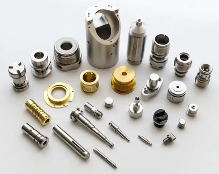
Product Description
|
Material |
1) Aluminum: AL 6061-T6, 6063, 7075-T etc. |
|
2) Stainless steel: 303,304,316L, 17-4(SUS630) etc. |
|
|
3) Steel: 4140, Q235, Q345B,20#,45# etc. |
|
|
4) Titanium: TA1,TA2/GR2, TA4/GR5, TC4, TC18 etc. |
|
|
5) Brass: C36000 (HPb62), C37700 (HPb59), C26800 (H68), C22000(H90) etc. |
|
|
6) Copper, bronze, Magnesium alloy, Delrin, POM,Acrylic, PC, etc. |
|
|
Finish |
Sandblasting, Anodize color, Blackenning, Zinc/Nickl Plating, Polish. |
|
Power coating, Passivation PVD, Titanium Plating, Electrogalvanizing. |
|
|
Electroplating chromium, electrophoresis, QPQ(Quench-Polish-Quench). |
|
|
Electro Polishing,Chrome Plating, Knurl, Laser etch Logo, etc. |
|
|
Main Equipment |
CNC Machining center(Milling), CNC Lathe, Grinding machine. |
|
Cylindrical grinder machine, Drilling machine, Laser Cutting Machine,etc. |
|
|
Drawing format |
STEP,STP,GIS,CAD,PDF,DWG,DXF etc or samples. |
|
Tolerance |
+/-0.01mm ~ +/-0.05mm |
|
Surface roughness |
Ra 0.1~3.2 |
|
Inspection |
Complete inspection lab with Micrometer, Optical Comparator, Caliper Vernier,CMM. |
|
Depth Caliper Vernier, Universal Protractor, Clock Gauge, Internal Centigrade Gauge. |
|
|
Capacity |
CNC turning work range: φ0.5mm-φ150mm*300mm. |
|
CNC milling work range: 510mm*1571mm*500mm. |
| Application: | Fastener, Auto and Motorcycle Accessory, Hardware Tool, Machinery Accessory |
|---|---|
| Standard: | GB, EN, API650, China GB Code, JIS Code, TEMA, ASME |
| Surface Treatment: | Anodizing |
| Production Type: | Mass Production |
| Machining Method: | CNC Machining |
| Material: | Nylon, Steel, Plastic, Brass, Alloy, Copper, Aluminum, Iron |
| Samples: |
US$ 20/Piece
1 Piece(Min.Order) | |
|---|
| Customization: |
Available
| Customized Request |
|---|

Are there variations in PTO shaft designs for different types of machinery?
Yes, there are variations in PTO (Power Take-Off) shaft designs to accommodate the specific requirements of different types of machinery. PTO shafts are highly versatile and adaptable components used to transfer power from a power source, such as a tractor or engine, to driven machinery or equipment. The design variations in PTO shafts are necessary to ensure compatibility, efficiency, and safety in various applications. Here’s a detailed explanation of the different PTO shaft designs for different types of machinery:
1. Standard PTO Shafts: Standard PTO shafts are the most common design and are widely used in a variety of applications. They typically consist of a solid steel shaft with a universal joint at each end. These universal joints allow for angular misalignment between the power source and the driven machinery. Standard PTO shafts are suitable for applications where the distance between the power source and the driven machinery remains relatively fixed. They are commonly used in agricultural implements, such as mowers, balers, tillers, and seeders, as well as in industrial applications.
2. Telescopic PTO Shafts: Telescopic PTO shafts feature a telescoping design that allows for length adjustment. These shafts consist of two or more concentric shafts that can slide within each other. Telescopic PTO shafts are beneficial in applications where the distance between the power source and the driven machinery varies. By adjusting the length of the shaft, operators can ensure proper power transmission without the risk of the shaft dragging on the ground or being too short to reach the equipment. Telescopic PTO shafts are commonly used in front-mounted implements, snow blowers, self-loading wagons, and other applications where the distance between the power source and the implement changes.
3. CV (Constant Velocity) PTO Shafts: CV PTO shafts incorporate Constant Velocity joints to accommodate misalignment and angular variations. These joints maintain a constant speed and torque transfer even when the driven machinery is at an angle relative to the power source. CV PTO shafts are beneficial in applications where the driven machinery requires flexibility and a wide range of movement. They are commonly used in articulated loaders, telescopic handlers, self-propelled sprayers, and other equipment that requires continuous power transmission while operating at various angles.
4. Gearbox Driven PTO Shafts: Some machinery requires specific speed or torque ratios between the power source and the driven equipment. In such cases, PTO shafts may incorporate gearbox systems. Gearbox driven PTO shafts allow for speed reduction or increase and can change the rotational direction if necessary. The gear ratios in the gearbox can be adjusted to match the speed and torque requirements of the driven machinery. These PTO shafts are commonly used in applications where the power source operates at a different speed or torque level than the equipment it drives, such as in certain industrial manufacturing processes and specialized machinery.
5. High-Torque PTO Shafts: Some heavy-duty machinery requires high torque levels for power transmission. High-torque PTO shafts are designed to handle these demanding applications. They are constructed with reinforced components, including larger diameter shafts and heavier-duty universal joints, to withstand the increased torque requirements. High-torque PTO shafts are commonly used in equipment such as wood chippers, crushers, and heavy-duty agricultural implements that require substantial power and torque for their operation.
6. Safety PTO Shafts: Safety is a crucial consideration when using PTO shafts. Safety PTO shafts incorporate mechanisms to reduce the risk of accidents and injuries. One common safety feature is the use of protective guards that cover the rotating shaft to prevent accidental contact. These guards are typically made of metal or plastic and are designed to shield the rotating components while allowing the necessary movement for power transmission. Safety PTO shafts are used in various applications where the risk of entanglement or accidental contact with the rotating shaft is high, such as in grass mowers, rotary cutters, and other equipment used in landscaping and agriculture.
These are some of the key variations in PTO shaft designs for different types of machinery. The specific design used depends on factors such as the application requirements, power source characteristics, torque levels, movement flexibility, and safety considerations. PTO shaft manufacturers offer a range of designs to ensure compatibility and efficient power transmission in diverse industries and applications.

Are there any limitations or disadvantages associated with PTO shafts?
While PTO (Power Take-Off) shafts offer numerous advantages in terms of power transfer and versatility, they also have certain limitations and disadvantages. It’s important to consider these factors when using PTO shafts to ensure safe and efficient operation. Here’s a detailed explanation of some limitations and disadvantages associated with PTO shafts:
1. Safety Hazards: One of the primary concerns with PTO shafts is the potential for safety hazards. PTO shafts rotate at high speeds and can pose a significant risk if not properly guarded or handled. Accidental contact with an exposed or inadequately shielded PTO shaft can result in severe injuries, including entanglement, amputation, or even fatalities. It is crucial to follow safety guidelines, implement proper guarding, and ensure that operators are well-trained on safe handling practices to mitigate these risks.
2. Maintenance and Lubrication: PTO shafts require regular maintenance and lubrication to ensure optimal performance and longevity. The moving parts, such as universal joints and splines, need to be inspected, cleaned, and lubricated at recommended intervals. Neglecting maintenance can lead to premature wear, decreased efficiency, and potential failures. Proper maintenance practices, including regular inspections and timely lubrication, are essential to mitigate these issues.
3. Alignment and Angles: PTO shafts rely on proper alignment and angles to ensure efficient power transfer. Misalignment or excessive angles between the power source and driven machinery can cause increased wear and strain on the components, leading to premature failure. Ensuring proper alignment and angle adjustment, using adjustable sliding yokes or other means, is important to prevent excessive stress on the PTO shaft and associated equipment.
4. Length Limitations: PTO shafts have limitations on their maximum and minimum length due to engineering constraints. The telescoping design allows for some adjustment, but there is a practical limit to how much the shaft can extend or retract. If the distance between the power source and driven machinery exceeds the maximum or falls below the minimum length of the PTO shaft, alternative solutions or modifications may be required. In some cases, additional components such as drive shaft extensions or gearboxes may be necessary to bridge the distance.
5. Compatibility: While manufacturers strive to ensure compatibility, there can still be challenges in finding the right PTO shaft for specific equipment configurations. Equipment may have unique requirements in terms of spline sizes, torque ratings, or connection methods that may not be readily available or compatible with off-the-shelf PTO shafts. Customization may be required to address these compatibility issues, which can result in increased costs or lead times.
6. Noise and Vibrations: PTO shafts in operation can generate significant noise and vibrations, especially at higher speeds. This can be a nuisance for operators and may require additional measures to reduce noise levels or dampen vibrations. Excessive vibrations can also affect the overall performance and lifespan of the PTO shaft and connected equipment. Implementing vibration dampeners or using flexible couplings can help mitigate these issues.
7. Power Limits: PTO shafts have specific power limits based on their design, materials, and components. Exceeding these power limits can lead to premature wear, component failures, or even shaft breakage. It is crucial to understand and adhere to the recommended power ratings for PTO shafts to ensure safe and reliable operation. In some cases, upgrading to a higher-capacity PTO shaft or implementing additional power transmission components may be necessary to accommodate higher power requirements.
8. Complex Installation and Removal: Installing and removing PTO shafts can be a complex process, especially in confined spaces or when dealing with heavy equipment. It may require aligning splines, engaging couplings, and securing locking mechanisms. Improper installation or removal techniques can lead to damage to the shaft or associated equipment. Proper training, handling equipment, and following manufacturer guidelines are essential to simplify and ensure the safe installation and removal of PTO shafts.
Despite these limitations and disadvantages, PTO shafts remain widely used and valuable components for power transfer in various industries. By addressing these considerations and implementing proper safety measures, maintenance practices, and alignment procedures, the potential drawbacks of PTO shafts can be effectively mitigated, allowing for safe and efficient operation.
Can you explain the different types of PTO shafts and their applications?
PTO shafts (Power Take-Off shafts) come in various types, each designed for specific applications and requirements. The different types of PTO shafts offer versatility and compatibility with a wide range of machinery and implements. Here’s an explanation of the most common types of PTO shafts and their applications:
1. Standard PTO Shaft: The standard PTO shaft, also known as a splined shaft, is the most common type used in agricultural and industrial machinery. It consists of a solid steel shaft with splines or grooves along its length. The standard PTO shaft typically has six splines, although variations with four or eight splines can be found. This type of PTO shaft is widely used in tractors and various implements, including mowers, balers, tillers, and rotary cutters. The splines provide a secure connection between the power source and the driven machinery, ensuring efficient power transfer.
2. Shear Bolt PTO Shaft: Shear bolt PTO shafts are designed with a safety feature that allows the shaft to separate in case of overload or sudden shock to protect the driveline components. These PTO shafts incorporate a shear bolt mechanism that connects the tractor’s power take-off to the driven machinery. In the event of excessive load or sudden resistance, the shear bolt is designed to break, disconnecting the PTO shaft and preventing damage to the driveline. Shear bolt PTO shafts are commonly used in equipment that may encounter sudden obstructions or high-stress situations, such as wood chippers, stump grinders, and heavy-duty rotary cutters.
3. Friction Clutch PTO Shaft: Friction clutch PTO shafts feature a clutch mechanism that allows for smooth engagement and disengagement of the power transfer. These PTO shafts typically incorporate a friction disc and a pressure plate, similar to a traditional vehicle clutch system. The friction clutch allows operators to gradually engage or disengage the power transfer, reducing shock loads and minimizing wear on the driveline components. Friction clutch PTO shafts are commonly used in applications where precise control of power engagement is required, such as in hydraulic pumps, generators, and industrial mixers.
4. Constant Velocity (CV) PTO Shaft: Constant Velocity (CV) PTO shafts, also known as homokinetic shafts, are designed to accommodate high angles of misalignment without affecting power transmission. They use a universal joint mechanism that allows for smooth power transfer even when the driven machinery is at an angle relative to the power source. CV PTO shafts are frequently used in applications where the machinery requires a significant range of movement or articulation, such as in articulated loaders, telescopic handlers, and self-propelled sprayers.
5. Telescopic PTO Shaft: Telescopic PTO shafts are adjustable in length, allowing for flexibility in equipment configuration and varying distances between the power source and the driven machinery. They consist of two or more concentric shafts that slide within each other, providing the ability to extend or retract the PTO shaft as needed. Telescopic PTO shafts are commonly used in applications where the distance between the tractor’s power take-off and the implement varies, such as in front-mounted implements, snow blowers, and self-loading wagons. The telescopic design enables easy adaptation to different equipment setups and minimizes the risk of the PTO shaft dragging on the ground.
6. Gearbox PTO Shaft: Gearbox PTO shafts are designed to adapt power transmission between different rotational speeds or directions. They incorporate a gearbox mechanism that allows for speed reduction or increase, as well as the ability to change rotational direction. Gearbox PTO shafts are commonly used in applications where the driven machinery requires a different speed or rotational direction than the tractor’s power take-off. Examples include grain augers, feed mixers, and industrial equipment that requires specific speed ratios or reversing capabilities.
It’s important to note that the availability and specific applications of PTO shaft types may vary based on regional and industry-specific factors. Additionally, certain machinery or implements may require specialized or custom PTO shafts to meet specific requirements.
In summary, the different types of PTO shafts, such as standard, shear bolt, friction clutch, constant velocity (CV), telescopic, and gearbox shafts, offer versatility and compatibility with various machinery and implements. Each type of PTO shaft is designed to address specific needs, such as power transfer efficiency, safety, smooth engagement, misalignment tolerance, adaptability, and speed/direction adjustment. Understanding the different types of PTO shafts and their applications is crucial for selecting the appropriate shaft forthe intended machinery and ensuring optimal performance and reliability.
editor by CX 2023-09-21
China OEM motor planer kubota pto roller shaft manufacturer CNC machining turning aluminum shaft pto shaft parts
CNC Machining or Not: Cnc Machining
Kind: Broaching, DRILLING, Etching / Chemical Machining, Laser Machining, Milling, Other Machining Services, Turning, Wire EDM, Fast Prototyping
Material Capabilities: Aluminum, Brass, Bronze, Copper, Hardened Metals, Precious Metals, Stainless steel, Metal Alloys
Micro Machining or Not: Micro Machining
Solution title: Made in China substantial precision CNC machining turning aluminum shaft
Key word: turning and machining precision parts
Approach: Cnc Machining Heart
Sample: Make Sample Inside of 7days
QC Control: one hundred% QC Methods Inspection
Measurement: Tailored Measurement
Surface area treatment: Customer’s Request
MOQ: 100pcs
Materials Avaliable: Stainless Steel Aluminum Metals Copper
Packing: Wood Circumstance/Carton
Packaging Information: carton or wooden case
Port: ZheJiang ,HangZhou
Merchandise Description Specification OEM & ODM metallic sheet fabrication, Customized fabrication 1. Material available Stainless steel 304, 304L ,316 ,316L ,430 ,201,etcAluminum 7075,6061,5052,2571,and so forth Brass H62 , H59 Steel C20, C45, C60, C35, Q235.. Stell Alloy 25CrMo, 42CrMo, 25Cr, 40Cr, Q345,11SMn30.. Iron Cast QT600, QT250, HT450, HT150… All the supplies are with the material good quality certificate, we are familiarwith the intercontinental materials norm and the substance substitute quality two. Tolerance: inside +/-.01mm3. Surface area treatment method: Plating 3+Cr,anti-corrosion optimum 480 hrs salt spray take a look at Coating powder coating,electrial coating Portray Exposy painting Polish Satin polish,mirror polish, electrial polish Anodizing Challenging anodizing,a variety of shade, Warmth remedy according to drawing need Advocate Merchandise Welcome to HangZhou Chuntai Environmental Safety Mechanical Engineering Co., Ltd.If you have task requirements,remember to really feel free to contact me! why select us HangZhou Chuntai Environmental Defense Equipment Engineering Co., Ltd. was set up in 1990, masking an area of practically 20000 square meters. It is located on the South Bank of the golden waterway of the Yangtze River, close to ZheJiang , withconvenient water and land transportation.The business has cooperated with universities, colleges and universities, Ministry of mechanization sector, Study Institute,American PLC firm, RSL business, drinking water organization, squander merchandise firm, French nationwide normal firm, Hong Kong Ecco company, and many others. Firm advantages:The company has sturdy technical force, sturdy detection method and powerful machining ability. The goods in the processing workshop are mostly bought to Japan, Sweden, Denmark, the United States, France and other places. Our factory has several well-known Japanese Sanqi Mazak and CNC lathes with complete equipment and vast operating selection of large-precision equipment resources, which can be made and processed according to different specifications of clients. Our company has robust specialized pressure and full evaluation methods Gear potential&inspection Our provider Person 1st,Quality 1st,Track record First,Support 1st! one. We are a professional manufacturer specializing in producing different steel areas, like CNC precision automated lathe machined areas, automatic lathe elements, milling machined components, wire chopping machined areas etc. 2.With knowledgeable technological engineers and modern day inspection gear.3.We are committed to focusing on the client’s need and satisfaction, and to offering substantial quality merchandise at aggressive charges in accordance to your drawings or samples. Special elements for your unique wants!four.Our strong R&D and QC division can manage the products to fulfill your rigorous requirment, a hundred% inspection on criticaldimensions with substantial precision +/-.01-.005mm. Packing & Shipping We place the items in carton or picket scenario.We stick to the demands of our buyers.Our sample will deliver to consumers in 7-10 times.Batch items will arrive inside 12-fifteen days soon after the sample is sent. To greater make sure the protection of your items, professional, environmentally helpful, convenient and productive packaging solutions will be provided. FAQ 1. who are we?We are based mostly in ZheJiang , China, commence from 1990,sell to Domestic Market(seventy eight.00%),Southeast Asia(ten.00%),NorthAmerica(5.00%),Japanese Europe(00.00%),Africa(00.00%),Oceania(00.00%),Eastern Asia(00.00%),Western Europe(00.00%),SouthernEurope(00.00%),South Asia(00.00%). There are total about 51-one hundred individuals in our place of work.2. how can we assure quality?Usually a pre-manufacturing sample prior to mass productionAlways ultimate Inspection ahead of shipment.three.what can you buy from us?Steel Processing,Foods Squander Disposal Equipment,Drinking water Therapy Products.4. why should you acquire from us not from other suppliers?Companies which integrates analysis and design and style, production, installation and commissioning, right after-income support , and who undertake huge turnkey venture of steel structure, stainless steel items of products.5. what solutions can we provide?Acknowledged Supply Phrases: FOB,CFR,CIF,EXW,DDP,Categorical Delivery;Accepted Payment Currency:USD,EURAccepted Payment Variety: T/T,L/C,Credit history Card,PayPal,Western UnionLanguage Spoken:English,Chinese,Japanese,German,Russian
An Overview of Worm Shafts and Gears
This article provides an overview of worm shafts and gears, including the type of toothing and deflection they experience. Other topics covered include the use of aluminum versus bronze worm shafts, calculating worm shaft deflection and lubrication. A thorough understanding of these issues will help you to design better gearboxes and other worm gear mechanisms. For further information, please visit the related websites. We also hope that you will find this article informative.
Double throat worm gears
The pitch diameter of a worm and the pitch of its worm wheel must be equal. The two types of worm gears have the same pitch diameter, but the difference lies in their axial and circular pitches. The pitch diameter is the distance between the worm’s teeth along its axis and the pitch diameter of the larger gear. Worms are made with left-handed or right-handed threads. The lead of the worm is the distance a point on the thread travels during one revolution of the worm gear. The backlash measurement should be made in a few different places on the gear wheel, as a large amount of backlash implies tooth spacing.
A double-throat worm gear is designed for high-load applications. It provides the tightest connection between worm and gear. It is crucial to mount a worm gear assembly correctly. The keyway design requires several points of contact, which block shaft rotation and help transfer torque to the gear. After determining the location of the keyway, a hole is drilled into the hub, which is then screwed into the gear.
The dual-threaded design of worm gears allows them to withstand heavy loads without slipping or tearing out of the worm. A double-throat worm gear provides the tightest connection between worm and gear, and is therefore ideal for hoisting applications. The self-locking nature of the worm gear is another advantage. If the worm gears are designed well, they are excellent for reducing speeds, as they are self-locking.
When choosing a worm, the number of threads that a worm has is critical. Thread starts determine the reduction ratio of a pair, so the higher the threads, the greater the ratio. The same is true for the worm helix angles, which can be one, two, or three threads long. This varies between a single thread and a double-throat worm gear, and it is crucial to consider the helix angle when selecting a worm.
Double-throat worm gears differ in their profile from the actual gear. Double-throat worm gears are especially useful in applications where noise is an issue. In addition to their low noise, worm gears can absorb shock loads. A double-throat worm gear is also a popular choice for many different types of applications. These gears are also commonly used for hoisting equipment. Its tooth profile is different from that of the actual gear.
Bronze or aluminum worm shafts
When selecting a worm, a few things should be kept in mind. The material of the shaft should be either bronze or aluminum. The worm itself is the primary component, but there are also addendum gears that are available. The total number of teeth on both the worm and the addendum gear should be greater than forty. The axial pitch of the worm needs to match the circular pitch of the larger gear.
The most common material used for worm gears is bronze because of its desirable mechanical properties. Bronze is a broad term referring to various copper alloys, including copper-nickel and copper-aluminum. Bronze is most commonly created by alloying copper with tin and aluminum. In some cases, this combination creates brass, which is a similar metal to bronze. The latter is less expensive and suitable for light loads.
There are many benefits to bronze worm gears. They are strong and durable, and they offer excellent wear-resistance. In contrast to steel worms, bronze worm gears are quieter than their counterparts. They also require no lubrication and are corrosion-resistant. Bronze worms are popular with small, light-weight machines, as they are easy to maintain. You can read more about worm gears in CZPT’s CZPT.
Although bronze or aluminum worm shafts are the most common, both materials are equally suitable for a variety of applications. A bronze shaft is often called bronze but may actually be brass. Historically, worm gears were made of SAE 65 gear bronze. However, newer materials have been introduced. SAE 65 gear bronze (UNS C90700) remains the preferred material. For high-volume applications, the material savings can be considerable.
Both types of worms are essentially the same in size and shape, but the lead on the left and right tooth surfaces can vary. This allows for precise adjustment of the backlash on a worm without changing the center distance between the worm gear. The different sizes of worms also make them easier to manufacture and maintain. But if you want an especially small worm for an industrial application, you should consider bronze or aluminum.
Calculation of worm shaft deflection
The centre-line distance of a worm gear and the number of worm teeth play a crucial role in the deflection of the rotor. These parameters should be entered into the tool in the same units as the main calculation. The selected variant is then transferred to the main calculation. The deflection of the worm gear can be calculated from the angle at which the worm teeth shrink. The following calculation is helpful for designing a worm gear.
Worm gears are widely used in industrial applications due to their high transmittable torques and large gear ratios. Their hard/soft material combination makes them ideally suited for a wide range of applications. The worm shaft is typically made of case-hardened steel, and the worm wheel is fabricated from a copper-tin-bronze alloy. In most cases, the wheel is the area of contact with the gear. Worm gears also have a low deflection, as high shaft deflection can affect the transmission accuracy and increase wear.
Another method for determining worm shaft deflection is to use the tooth-dependent bending stiffness of a worm gear’s toothing. By calculating the stiffness of the individual sections of a worm shaft, the stiffness of the entire worm can be determined. The approximate tooth area is shown in figure 5.
Another way to calculate worm shaft deflection is by using the FEM method. The simulation tool uses an analytical model of the worm gear shaft to determine the deflection of the worm. It is based on a two-dimensional model, which is more suitable for simulation. Then, you need to input the worm gear’s pitch angle and the toothing to calculate the maximum deflection.
Lubrication of worm shafts
In order to protect the gears, worm drives require lubricants that offer excellent anti-wear protection, high oxidation resistance, and low friction. While mineral oil lubricants are widely used, synthetic base oils have better performance characteristics and lower operating temperatures. The Arrhenius Rate Rule states that chemical reactions double every ten degrees C. Synthetic lubricants are the best choice for these applications.
Synthetics and compounded mineral oils are the most popular lubricants for worm gears. These oils are formulated with mineral basestock and four to six percent synthetic fatty acid. Surface-active additives give compounded gear oils outstanding lubricity and prevent sliding wear. These oils are suited for high-speed applications, including worm gears. However, synthetic oil has the disadvantage of being incompatible with polycarbonate and some paints.
Synthetic lubricants are expensive, but they can increase worm gear efficiency and operating life. Synthetic lubricants typically fall into two categories: PAO synthetic oils and EP synthetic oils. The latter has a higher viscosity index and can be used at a range of temperatures. Synthetic lubricants often contain anti-wear additives and EP (anti-wear).
Worm gears are frequently mounted over or under the gearbox. The proper lubrication is essential to ensure the correct mounting and operation. Oftentimes, inadequate lubrication can cause the unit to fail sooner than expected. Because of this, a technician may not make a connection between the lack of lube and the failure of the unit. It is important to follow the manufacturer’s recommendations and use high-quality lubricant for your gearbox.
Worm drives reduce backlash by minimizing the play between gear teeth. Backlash can cause damage if unbalanced forces are introduced. Worm drives are lightweight and durable because they have minimal moving parts. In addition, worm drives are low-noise and vibration. In addition, their sliding motion scrapes away excess lubricant. The constant sliding action generates a high amount of heat, which is why superior lubrication is critical.
Oils with a high film strength and excellent adhesion are ideal for lubrication of worm gears. Some of these oils contain sulfur, which can etch a bronze gear. In order to avoid this, it is imperative to use a lubricant that has high film strength and prevents asperities from welding. The ideal lubricant for worm gears is one that provides excellent film strength and does not contain sulfur.


editor by czh
Best China manufacturer & factory Professional Customized cnc turning parts machining two stages spur gear With high quality best price

“We are always serving our customers with our best products.”
Overview
Quick Details
- Applicable Industries:
-
Manufacturing Plant
- Brand Name:
-
OEM
- OEM Service:
-
Support
- Tolerance:
-
0.01-0.05mm or Customized
- CertificaOur strength lies in flexible production processes such as turning/milling, hard-turning, cylindrical grinding, gear cutting, erosion, generating grinding, and profile grinding, which we perform to the highest quality standards. A further core competency is our in-house heat treatment facility, where gearing components are annealed, case-hardened and cryogenically treated. Each hardened batch is tested with regard to surface hardness, case depth, and, where appropriate, microstructure condition at our in-house material testing lab. Even highly complex shape and position tolerances as well as gearing qualities can be ensured at our category 3 testing room using Zeiss and Klingelnberg measuring machines.tion:
-
ISO9001, SGS
- Surface Treatment:
-
Sandblasting,Polishing,Anodize, Zinc,Nickel,Chrome,Plating, etc.
- Application:
-
Automobile,Medical Equipments,Electric Appliance,Hardware,etc.
- Dimension:
-
As Customers’ Request
- “EPG” brand rotocultivator ploughshares in T.S. total lines produced in our factory have been tested and appraised by the Ministry of Agriculture and have obtained the license of popularizing farm machinery promulgated by the Ministry of Agriculture of the People’s Republic of China. Equipment:
-
Milling/Lathe/Drilling/Four/Three Axis CNC Machining Center
- Drawing Format:
-
PRO/E, Auto CAD, Solid Works,IGS,UG, CAD/CAM/CAE
Supply Ability
- Supply Ability:
- 10000 Piece/Pieces per Month
Packaging & Delivery
- Port
- nb
-
Lead Time
: -
Quantity(Pieces) 1 – 500 >500 Est. Time(days) 30 To be negotiated
Online Customization
Professional Customized cnc turning parts machining two stages spur gear
Product Description
| Product Type | CNC turning, milling, drilling, grinding, wire EDM cutting etc. |
| Our Services | CNC Machining,Plastic Injection,Stamping,Die Casting,Silicone And Rubber,Aluminum Extrusion,Mould Making,etc |
| Material | Aluminum,Brass,Stainless Steel,Copper,Plastic,Wood,Silicone,Rubber,Or as per the customers’ requirements |
| Surface Treatment |
Anodizing,Sandblasting,Painting,Powder coating,Plating,Silk Printing,Brushing,Polishing,Laser Engraving |
| Dimension | As customers’ request |
| Service Project | To provide production design, production and technical service, mould development and processing, etc |
| Drawing Format: | PRO/E, Auto CAD, Solid Works,IGS,UG, CAD/CAM/CAE |
| Testing Machine | Digital Height Gauge, caliper, Coordinate measuring machine, projection machine, roughness tester, hardness tester and so on |
| Industry used | Machinery; heavy duty equipment; electronic device; Auto spare parts; optical telecommunication |
| Packing | Eco-friendly pp bag / EPE Foam /Carton boxes or wooden boxes AsAT series with tri-lobe tube (triangular) The triangular tube shape is the most used, from lightweight to fairly heavy applications. In the case of applications with high sliding, the R version with Rilsan coating is also available. AL series with two-lobe tubes (lemon). customer’s specific requirements |
| Trial sample time | 7-10 days after confirmation |
| Delivery time | 7-30 days after receive the pre-payments |
| Payment Terms | T/T,Western Union,Paypal |
More service
OEM Parts
Surface Treatment
Production Process
Why Us